| Part No | Figure / Lead Option |
lhold (A) | Itrip (A) |
Vmax (V) |
Imax (A) |
Pd typ (W) |
Max. (A) |
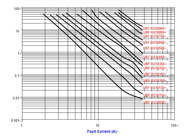
Time-to-trip (s) |
R min (Ω) |
R1 Max (Ω) |
|
| UBF | RU30090 | Fig. 1, Ø0.51, Sn/CuFe | 0.90 | 1.8 | 30 | 40 | 0.6 | 4.5 | 5.9 | 0.070 | 0.22 |
| UBF | RU30110 | Fig. 1, Ø0.51, Sn/CuFe | 1.10 | 2.2 | 30 | 40 | 0.7 | 5.5 | 6.6 | 0.050 | 0.17 |
| UBF | RU30135 | Fig. 1, Ø0.51, Sn/CuFe | 1.35 | 2.7 | 30 | 40 | 0.8 | 6.75 | 7.3 | 0.040 | 0.13 |
| UBF | RU30160 | Fig. 1, Ø0.51, Sn/CuFe | 1.60 | 3.2 | 30 | 40 | 0.9 | 8.5 | 8.0 | 0.030 | 0.11 |
| UBF | RU30185 | Fig. 1, Ø0.51, Sn/CuFe | 1.85 | 3.7 | 30 | 40 | 1.0 | 9.25 | 8.7 | 0.030 | 0.09 |
| UBF | RU30250 | Fig. 2, Ø0.81, Sn/CuFe | 2.50 | 5.0 | 30 | 40 | 1.2 | 12.5 | 10.3 | 0.020 | 0.07 |
| UBF | RU30300 | Fig. 2, Ø0.81, Sn/CuFe | 3.0 | 6.0 | 30 | 40 | 2.0 | 15.0 | 10.8 | 0.020 | 0.08 |
| UBF | RU30400 | Fig. 2, Ø0.81, Sn/CuFe | 4.0 | 8.0 | 30 | 40 | 2.5 | 20.0 | 12.7 | 0.010 | 0.05 |
| UBF | RU30500 | Fig. 2, Ø0.81, Sn/CuFe | 5.0 | 10.0 | 30 | 40 | 3.0 | 25.0 | 14.5 | 0.010 | 0.05 |
| UBF | RU30600 | Fig. 2, Ø0.81, Sn/CuFe | 6.0 | 12.0 | 30 | 40 | 3.5 | 30.0 | 16.0 | 0.005 | 0.04 |
| UBF | RU30700 | Fig. 2, Ø0.81, Sn/CuFe | 7.0 | 14.0 | 30 | 40 | 3.8 | 35.0 | 17.5 | 0.005 | 0.03 |
| UBF | RU30800 | Fig. 2, Ø0.81, Sn/CuFe | 8.0 | 16.0 | 30 | 40 | 4.0 | 40.0 | 18.8 | 0.005 | 0.02 |
| UBF | RU30900 | Fig. 2, Ø0.81, Sn/CuFe | 9.0 | 18.0 | 30 | 40 | 4.2 | 45.0 | 20.0 | 0.005 | 0.02 |
| Ihold | Hold current is the maximum current that UB Fuse can pass through without interruption at 20°C unless otherwise specified. |
| Itrip | Trip current is the minimum current that will switch the device from low resistance state to high resistance state at 20°C unless specified. |
| Vmax | The maximum voltage device can withstand without damage at rated current. |
| Imax | The maximum current device can withstand without damage at rated voltage. |
| Pd | The power dissipated from device when in the tripped state at 20°C unless otherwise specified. |
| R min | The minimum resistance of device as received from the factory at 20°C unless otherwise specified. |
| R max | The maximum resistance of device as received from the factory at 20°C unless otherwise specified. |
| R1max | The maximum resistance of device when measured one hour post trip at 20°C unless otherwise specified. |
| Max. Time-to-trip |
The maximum time for device to trip at specified current ratings at 20°C unless otherwise specified. |
| Test | Test Conditions | Resistance Change |
| Passive Aging | +85°C, 1000 hours | ±5% typical resistance change |
| Humidity Aging | +85°C, 85% R.H., 7 days | ±5% typical resistance change |
| Thermal Shock | +85°C to -40°C, 10 times MIL-STD-202, Method 107G |
±5% typical resistance change |
| Vibration | MIL-STD-883C, Condition A | No change |
| Solvent resistance | MIL-STD-202, Method 215 | No change |
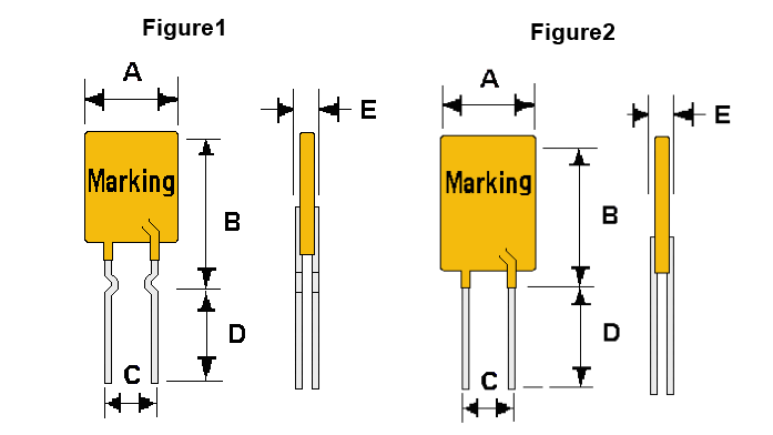
◆Dimensions
| A | B | C | D | E | ||
| Part No | Max. | Max. | Max. | Min. | Max. | Max. |
| UBF RU30090 | 7.4 | 12.7 | 4.3 | 5.8 | 7.6 | 3.0 |
| UBF RU30110 | 7.4 | 12.7 | 4.3 | 5.8 | 7.6 | 3.0 |
| UBF RU30135 | 7.4 | 12.7 | 4.3 | 5.8 | 7.6 | 3.0 |
| UBF RU30160 | 7.4 | 12.7 | 4.3 | 5.8 | 7.6 | 3.0 |
| UBF RU30185 | 7.4 | 12.7 | 4.3 | 5.8 | 7.6 | 3.0 |
| UBF RU30250 | 7.6 | 13.5 | 4.3 | 5.8 | 7.6 | 3.0 |
| UBF RU30300 | 7.9 | 13.7 | 4.3 | 5.8 | 7.6 | 3.0 |
| UBF RU30400 | 9.4 | 14.5 | 4.3 | 5.8 | 7.6 | 3.0 |
| UBF RU30500 | 10.2 | 15.2 | 4.3 | 5.8 | 7.6 | 3.0 |
| UBF RU30600 | 11.2 | 15.8 | 4.3 | 5.8 | 7.6 | 3.0 |
| UBF RU30700 | 12.8 | 17.5 | 4.3 | 5.8 | 7.6 | 3.0 |
| UBF RU30800 | 14.5 | 19.1 | 4.3 | 5.8 | 7.6 | 3.0 |
| UBF RU30900 | 16.3 | 20.8 | 4.3 | 5.8 | 7.6 | 3.0 |
| UL File Number | E 119550 |
| c-UL File Number | E 119550 |
| TUV File Number | Pending |
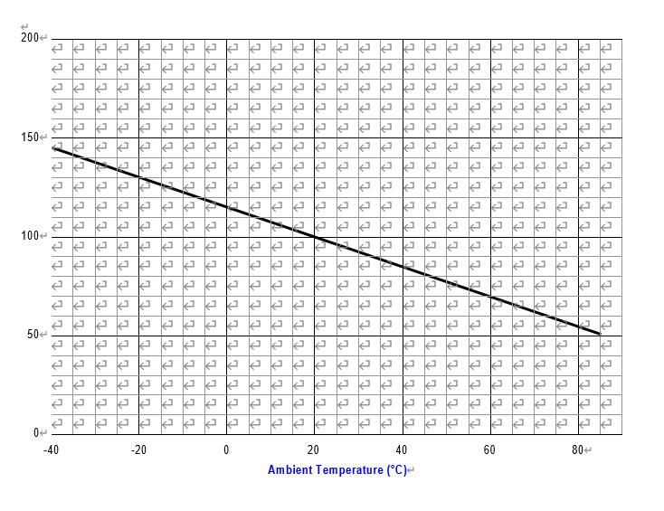
| Part No | -40 | -20 | 0 | 20 | 40 | 60 | 85 |
| UBF RU30090 | 1.32 | 1.17 | 1.04 | 0.90 | 0.75 | 0.61 | 0.47 |
| UBF RU30110 | 1.62 | 1.43 | 1.27 | 1.10 | 0.91 | 0.75 | 0.57 |
| UBF RU30135 | 1.98 | 1.76 | 1.55 | 1.35 | 1.12 | 0.92 | 0.70 |
| UBF RU30160 | 2.35 | 2.08 | 1.84 | 1.60 | 1.33 | 1.09 | 0.83 |
| UBF RU30185 | 2.72 | 2.41 | 2.13 | 1.85 | 1.54 | 1.26 | 0.96 |
| UBF RU30250 | 3.68 | 3.25 | 2.88 | 2.50 | 2.08 | 1.70 | 1.30 |
| UBF RU30300 | 4.41 | 3.90 | 3.45 | 3.00 | 2.49 | 2.04 | 1.56 |
| UBF RU30400 | 5.80 | 5.20 | 4.60 | 4.00 | 3.32 | 2.72 | 2.08 |
| UBF RU30500 | 7.35 | 6.50 | 5.75 | 5.00 | 4.15 | 3.40 | 2.60 |
| UBF RU30600 | 8.82 | 7.80 | 6.90 | 6.00 | 4.98 | 4.08 | 3.12 |
| UBF RU30700 | 10.25 | 9.10 | 8.05 | 7.00 | 5.81 | 4.76 | 3.64 |
| UBF RU30800 | 11.76 | 10.40 | 9.20 | 8.00 | 6.64 | 5.44 | 4.16 |
| UBF RU30900 | 13.23 | 11.70 | 10.35 | 9.00 | 7.47 | 6.12 | 4.68 |
| Part No | -1 Loose Pack Quantity | -2 Tape & Reel Quantity | -3 Ammo Pack Quantity |
| UBF RU30090 | 500 | 3000 | 2000 |
| UBF RU30110 | 500 | 3000 | 2000 |
| UBF RU30135 | 500 | 3000 | 2000 |
| UBF RU30160 | 500 | 3000 | 2000 |
| UBF RU30185 | 500 | 3000 | 2000 |
| UBF RU30250 | 500 | 3000 | 2000 |
| UBF RU30300 | 500 | 2500 | 1000 |
| UBF RU30400 | 500 | 1500 | 1000 |
| UBF RU30500 | 250 | 1500 | 1000 |
| UBF RU30600 | 250 | 1500 | 1000 |
| UBF RU30700 | 250 | 1500 | 1000 |
| UBF RU30800 | 250 | Not available | Not available |
| UBF RU30900 | 250 | Not available | Not available |
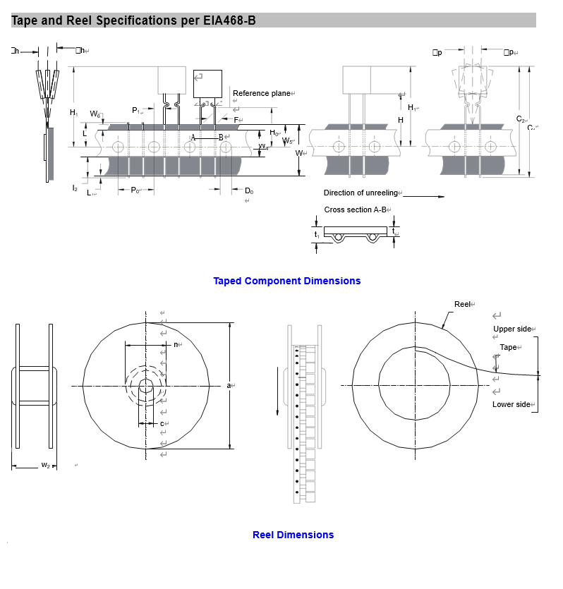
| Description | EIA Mark |
Dimension | Tolerance |
| Carrier tape width | W | 18 | -0.5/+1.0 |
| Hold-down tape width | W4 | 11 | Minimum |
| Top distance between tape edges | W6 | 3 | Maximum |
| Sprocket hole position | W5 | 9 | -0.5/+0.75 |
| Sprocket hole diameter | D0 | 4 | ±0.2 |
| Abscissa to plane (kinked lead) UBF RU30090 - 250 | H0 | 16.0 | ±0.5 |
| Abscissa to plane (straight lead) UBF RU30300 - 700 | H | 18.5 | ±2.5 |
| Abscissa to top UBF RU30090 - 300 | H1 | 32.2 | Maximum |
| Abscissa to top UBF RU30400 - 700 | H1 | 47.5 | Maximum |
| Overall width w/lead protrusion UBF RU30090 - 300 | C1 | 43.2 | Maximum |
| Overall width w/lead protrusion UBF RU30400 - 700 | C1 | 58 | Maximum |
| Overall width w/o lead protrusion UBF RU30090 - 300 | C2 | 42.5 | Maximum |
| Overall width w/o lead protrusion UBF RU30400 - 700 | C2 | 57 | Maximum |
| Lead protrusion | L1 | 1.0 | Maximum |
| Protrusion of cut-out | L | 11.0 | Maximum |
| Protrusion beyond hold-down tape | I2 | Not specified | -- |
| Sprocket hole pitch | P0 | 12.7 | ±0.3 |
| Device pitch UBF RU30090 - 300 | -- | 12.7 | ±0.3 |
| Device pitch UBF RU30400 - 700 | -- | 25.4 | ±0.6 |
| Pitch tolerance | -- | 20 consecutive | ±1 |
| Tape thickness | t | 0.9 | Maximum |
| Overall tape and lead thickness BFRU30090 - 250 | t1 | 1.5 | Maximum |
| Overall tape and lead thickness BFRU30300 - 700 | t1 | 2.3 | Maximum |
| Splice sprocket hole alignment | -- | 0 | ±0.3 |
| Body lateral deviation | △h | 0 | ±1.0 |
| Body tape plane deviation | △p | 0 | ±1.3 |
| Ordinate to adjacent component lead UBF RU30090 - 300 | P1 | 3.81 | ±0.7 |
| Ordinate to adjacent component lead UBF RU30400 - 700 | P1 | 7.62 | ±0.7 |
| Lead spacing UBF RU30090 - 400 | F | 5.08 | +0.75/-0.5 |
| Lead spacing UBF RU30500 - 700 | F | 10.2 | +0.75/-0.5 |
| Reel width UB FRU30090 - 400 | w2 | 56.0 | Maximum |
| Reel width UBF RU30500 - 700 | w2 | 63.5 | Maximum |
| Reel diameter | a | 370.0 | Maximum |
| Space between flanges less device | w1 | 4.75 | ±3.25 |
| Arbor hole diameter | c | 26.0 | ±12.0 |
| Core diameter | n | 91.0 | Maximum |
| Box | -- | 64/372/362 | Maximum |
| Consecutive missing places | -- | None | -- |
| Empty places per reel | -- | 0.1% | Maximum |