
| Part No | Figure / Lead Option |
lhold (A) | Itrip (A) |
Vmax (V) |
Imax (A) |
Pd typ (W) |
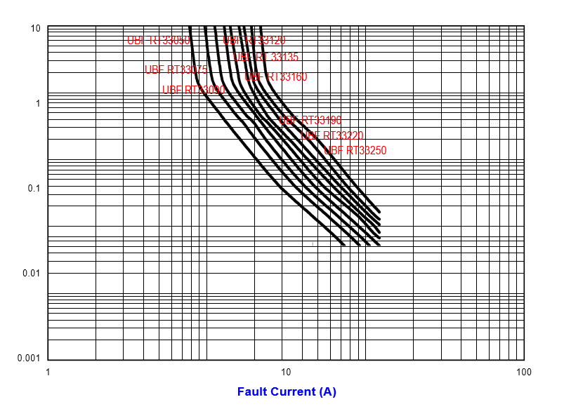
Max. (A) |
Time-to-trip (s) |
R min (Ω) |
R1 Max (Ω) |
|
| UBF | RT33050 | Fig. 1, Ø0.51, Sn/CuFe | 0.50 | 1.00 | 33 | 40 | 0.67 | 5.0 | 2.25 | 0.140 | 0.048 |
| UBF | RT33075 | Fig. 1, Ø0.51, Sn/CuFe | 0.75 | 1.50 | 33 | 40 | 0.71 | 4.0 | 3.75 | 0.115 | 0.368 |
| UBF | RT33090 | Fig. 1, Ø0.51, Sn/CuFe | 0.90 | 1.80 | 33 | 40 | 0.74 | 3.5 | 4.50 | 0.090 | 0.228 |
| UBF | RT33120 | Fig. 1, Ø0.51, Sn/CuFe | 1.20 | 2.30 | 33 | 40 | 0.78 | 3.5 | 6.00 | 0.074 | 0.180 |
| UBF | RT33135 | Fig. 1, Ø0.51, Sn/CuFe | 1.35 | 2.50 | 33 | 40 | 0.84 | 4.5 | 6.75 | 0.059 | 0.143 |
| UBF | RT33160 | Fig. 1, Ø0.51, Sn/CuFe | 1.60 | 2.75 | 33 | 40 | 0.86 | 4.5 | 8.00 | 0.041 | 0.131 |
| UBF | RT33190 | Fig. 2, Ø0.81, Sn/CuFe | 1.90 | 3.00 | 33 | 40 | 0.90 | 3.5 | 9.50 | 0.045 | 0.092 |
| UBF | RT33220 | Fig. 2, Ø0.81, Sn/CuFe | 2.20 | 3.50 | 33 | 40 | 0.95 | 6.5 | 11.00 | 0.025 | 0.080 |
| UBF | RT33250 | Fig. 2, Ø0.81, Sn/CuFe | 2.50 | 4.00 | 33 | 40 | 0.99 | 8.0 | 12.50 | 0.020 | 0.064 |
| Ihold | Hold current is the maximum current that UB Fuse can pass through without interruption at 20°C unless otherwise specified. |
| Itrip | Trip current is the minimum current that will switch the device from low resistance state to high resistance state at 20°C unless specified. |
| Vmax | The maximum voltage device can withstand without damage at rated current. |
| Imax | The maximum current device can withstand without damage at rated voltage. |
| Pd | The power dissipated from device when in the tripped state at 20°C unless otherwise specified. |
| R min | The minimum resistance of device as received from the factory at 20°C unless otherwise specified. |
| R max | The maximum resistance of device as received from the factory at 20°C unless otherwise specified. |
| R1max | The maximum resistance of device when measured one hour post trip at 20°C unless otherwise specified. |
| Max. Time-to-trip |
The maximum time for device to trip at specified current ratings at 20°C unless otherwise specified. |
| Test | Test Conditions | Resistance Change |
| Passive Aging | +85°C, 1000 hours | ±5% typical resistance change |
| Humidity Aging | +85°C, 85% R.H., 7 days | ±5% typical resistance change |
| Thermal Shock | +85°C to -40°C, 10 times MIL-STD-202, Method 107G |
±5% typical resistance change |
| Vibration | MIL-STD-883C, Condition A | No change |
| Solvent resistance | MIL-STD-202, Method 215 | No change |
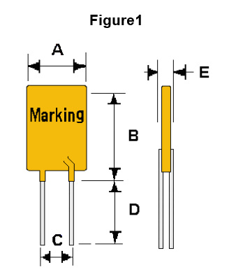
| A | B | C | D | E | F | |
| Part No | Max. | Max. | Typical | Min. | Max. | Typical |
| UBF RT33050 | 7.4 | 12.2 | 5.1 | 7.6 | 3.0 | 1.1 |
| UBF RT33075 | 7.4 | 12.2 | 5.1 | 7.6 | 3.0 | 1.1 |
| UBF RT33090 | 7.4 | 12.2 | 5.1 | 7.6 | 3.0 | 1.1 |
| UBF RT33120 | 7.4 | 12.2 | 5.1 | 7.6 | 3.0 | 1.1 |
| UBF RT33135 | 7.4 | 14.2 | 5.1 | 7.6 | 3.0 | 1.1 |
| UBF RT33160 | 7.4 | 14.0 | 5.1 | 7.6 | 3.0 | 1.1 |
| UBF RT33190 | 9.0 | 13.5 | 5.1 | 7.6 | 3.0 | 1.1 |
| UBF RT33220 | 10.0 | 17.5 | 5.1 | 7.6 | 3.0 | 1.1 |
| UBF RT33250 | 10.0 | 19.5 | 5.1 | 7.6 | 3.0 | 1.1 |
| UL File Number | E 119550 |
| c-UL File Number | E 119550 |
| TUV File Number | Pending |
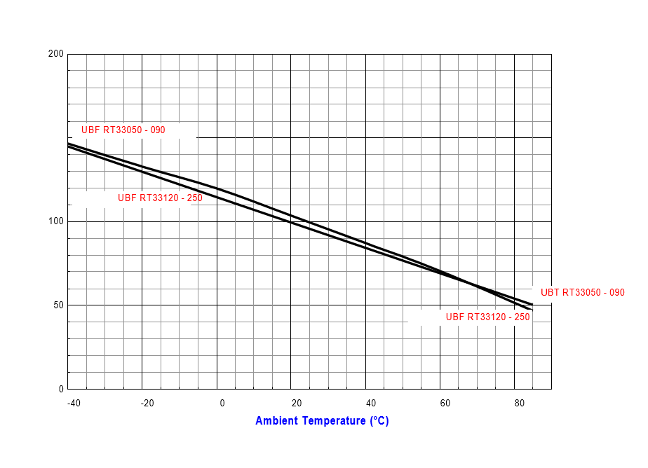
| Part No | -40 | -20 | 0 | 20 | 40 | 60 | 85 |
| UBF RT33050 | 0.74 | 0.68 | 0.60 | 0.50 | 0.45 | 0.39 | 0.32 |
| UBF RT33075 | 1.11 | 1.01 | 0.90 | 0.75 | 0.68 | 0.59 | 0.48 |
| UBF RT33090 | 1.33 | 1.22 | 1.08 | 0.90 | 0.81 | 0.70 | 0.58 |
| UBF RT33120 | 1.78 | 1.62 | 1.62 | 1.35 | 1.22 | 0.94 | 0.77 |
| UBF RT33135 | 2.00 | 1.82 | 1.62 | 1.35 | 1.22 | 1.05 | 0.86 |
| UBF RT33160 | 2.37 | 2.16 | 1.92 | 1.60 | 1.44 | 1.25 | 1.02 |
| UBF RT33190 | 2.81 | 2.57 | 2.28 | 1.90 | 1.71 | 1.48 | 1.22 |
| UBF RT33220 | 3.26 | 2.97 | 2.64 | 2.20 | 1.98 | 1.72 | 1.41 |
| UBF RT33250 | 3.70 | 3.38 | 3.00 | 2.50 | 2.25 | 1.95 | 1.60 |
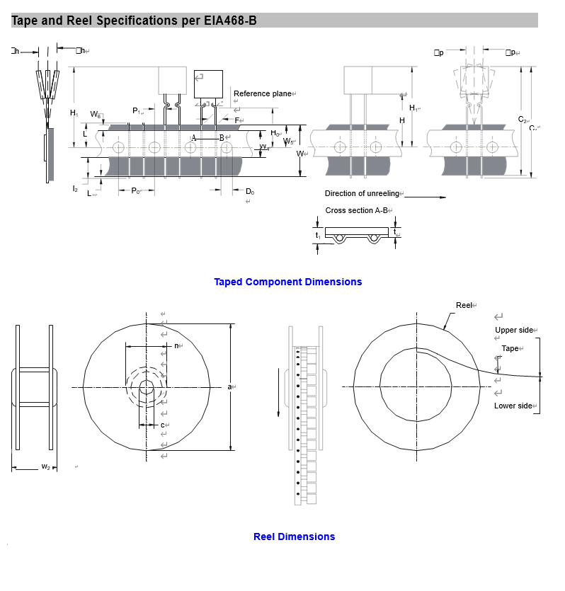
| Part No | -1 Loose Pack Quantity | -2 Tape & Reel Quantity | -3 Ammo Pack Quantity |
| UBF RT33050 | 500 | 3000 | 2000 |
| UBF RT33075 | 500 | 3000 | 2000 |
| UBF RT33090 | 500 | 3000 | 2000 |
| UBF RT33120 | 500 | 3000 | 2000 |
| UBF RT33135 | 500 | 2500 | 2000 |
| UBF RT33160 | 500 | 2500 | 2000 |
| UBF RT33190 | 500 | 2000 | 2000 |
| UBF RT33220 | 500 | 2000 | 2000 |
| UBF RT33250 | 500 | 1500 | 1500 |