| Part No | Figure | lhold (A) | Itrip (A) |
Vmax (V) |
Imax (A) |
Pd typ (W) |
Max. (A) |
Time-to-trip (s) |
R min (Ω) |
R Max (Ω) |
R1 Max (Ω) |
|
| UBF | LT070 | 1 | 0.7 | 1.45 | 15 | 100 | 0.7 | 3.5 | 5.0 | 0.100 | 0.200 | 0.340 |
| UBF | LT070S | 2 | 0.7 | 1.45 | 15 | 100 | 0.7 | 3.5 | 5.0 | 0.100 | 0.200 | 0.340 |
| UBF | LT100 | 1 | 1.0 | 2.50 | 24 | 100 | 0.9 | 5.0 | 7.0 | 0.070 | 0.130 | 0.260 |
| UBF | LT100S | 2 | 1.0 | 2.50 | 24 | 100 | 0.9 | 5.0 | 7.0 | 0.070 | 0.130 | 0.260 |
| UBF | LT100SS | 3 | 1.0 | 2.50 | 24 | 100 | 0.9 | 5.0 | 7.0 | 0.070 | 0.130 | 0.260 |
| UBF | LT180 | 1 | 1.8 | 3.80 | 24 | 100 | 1.0 | 9.0 | 2.9 | 0.040 | 0.068 | 0.120 |
| UBF | LT180S | 2 | 1.8 | 3.80 | 24 | 100 | 1.0 | 9.0 | 2.9 | 0.040 | 0.068 | 0.120 |
| UBF | LT190 | 1 | 1.9 | 4.20 | 24 | 100 | 1.9 | 10.0 | 3.0 | 0.030 | 0.057 | 0.100 |
| UBF | LT260 | 1 | 2.6 | 5.20 | 24 | 100 | 1.3 | 13.0 | 5.0 | 0.025 | 0.042 | 0.076 |
| UBF | LT300 | 1 | 3.0 | 6.30 | 24 | 100 | 1.7 | 15.0 | 4.0 | 0.015 | 0.031 | 0.055 |
| UBF | LT340 | 1 | 3.4 | 6.80 | 24 | 100 | 1.6 | 17.0 | 5.0 | 0.016 | 0.027 | 0.050 |
| Ihold | Hold current is the maximum current that UB Fuse can pass through without interruption at 20°C unless otherwise specified. |
| Itrip | Trip current is the minimum current that will switch the device from low resistance state to high resistance state at 20°C unless specified. |
| Vmax | The maximum voltage device can withstand without damage at rated current. |
| Imax | The maximum current device can withstand without damage at rated voltage. |
| Pd | The power dissipated from device when in the tripped state at 20°C unless otherwise specified. |
| R min | The minimum resistance of device as received from the factory at 20°C unless otherwise specified. |
| R max | The maximum resistance of device as received from the factory at 20°C unless otherwise specified. |
| R1max | The maximum resistance of device when measured one hour post trip at 20°C unless otherwise specified. |
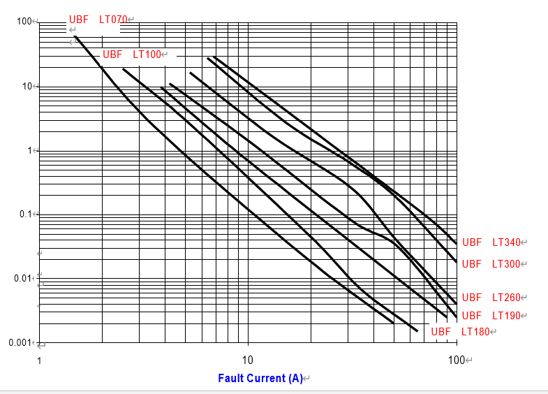
| Max. Time-to-trip |
The maximum time for device to trip at specified current ratings at 20°C unless otherwise specified. |
| Test | Test Conditions | Resistance Change |
| Passive Aging | +70°C, 1000 hours | ±10% typical resistance change |
| Humidity Aging | +85°C, 85% R.H., 7 days | ±15% typical resistance change |
| Thermal Shock | +85°C to -40°C, 10 times MIL-STD-202, Method 107G |
±+5% typical resistance change |
| Vibration | MIL-STD-883C, Condition A | No change |
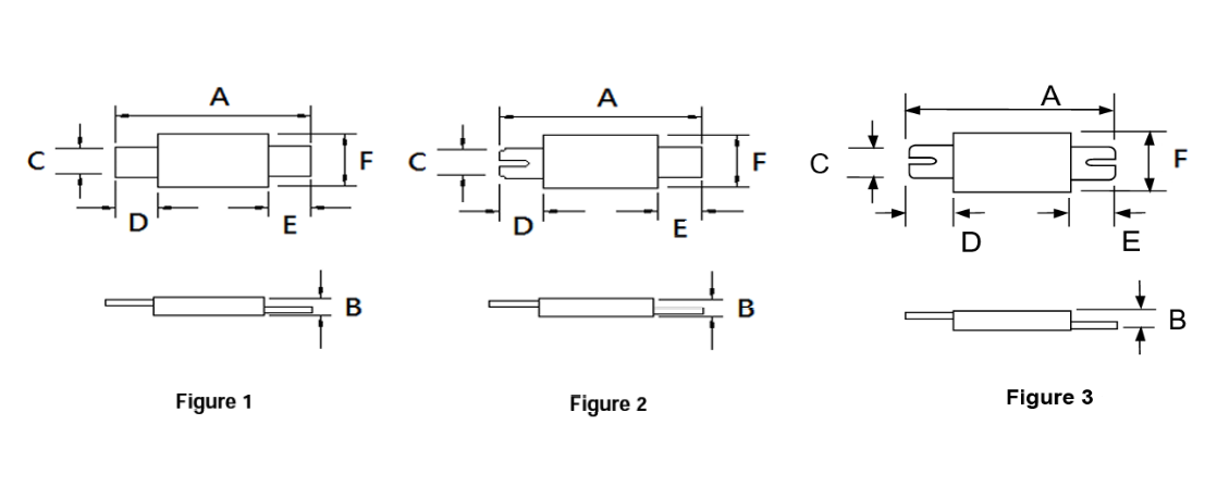
| A | B | C | D | E | F | |||||||
| Part No | Min. | Max. | Min. | Max. | Min. | Max. | Min. | Max. | Min. | Max. | Min. | Max. |
| UBF LT070 | 19.9 | 22.1 | 0.7 | 1.2 | 4.9 | 5.2 | 5.5 | 7.5 | 5.5 | 7.5 | 3.9 | 4.1 |
| UBF LT070S | 19.9 | 22.1 | 0.7 | 1.2 | 4.9 | 5.2 | 5.5 | 7.5 | 5.5 | 7.5 | 3.9 | 4.1 |
| UBF LT100 | 20.9 | 23.1 | 0.6 | 1.0 | 4.9 | 5.2 | 4.1 | 5.5 | 4.1 | 5.5 | 3.9 | 4.1 |
| UBF LT100S | 20.9 | 23.1 | 0.6 | 1.0 | 4.9 | 5.2 | 4.1 | 5.5 | 4.1 | 5.5 | 3.9 | 4.1 |
| UBF LT100SS | 20.9 | 23.1 | 0.6 | 1.0 | 4.9 | 5.2 | 4.1 | 5.5 | 4.1 | 5.5 | 3.9 | 4.1 |
| UBF LT180 | 24.0 | 26.0 | 0.6 | 1.0 | 4.9 | 5.2 | 4.1 | 5.5 | 4.1 | 5.5 | 3.9 | 4.1 |
| UBF LT180S | 24.0 | 26.0 | 0.6 | 1.0 | 4.9 | 5.2 | 4.1 | 5.5 | 4.1 | 5.5 | 3.9 | 4.1 |
| UBF LT190 | 21.3 | 23.4 | 0.5 | 1.1 | 10.2 | 11.0 | 5.0 | 7.6 | 5.0 | 7.6 | 4.8 | 5.4 |
| UBF LT260 | 24.0 | 26.0 | 0.6 | 1.0 | 10.8 | 11.9 | 5.0 | 7.0 | 5.0 | 7.0 | 5.9 | 6.1 |
| UBF LT300 | 28.4 | 31.8 | 0.5 | 1.1 | 13.0 | 13.5 | 6.3 | 8.9 | 6.3 | 8.9 | 6.0 | 6.6 |
| UBF LT340 | 24.0 | 26.0 | 0.6 | 1.0 | 14.8 | 15.9 | 4.0 | 5.0 | 4.0 | 5.0 | 5.9 | 6.1 |
| UL File Number | E 119550 |
| c-UL File Number | E 119550 |
| TUV File Number | Pending |
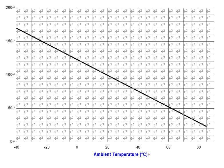
| Part No | -40 | -20 | 0 | 20 | 40 | 60 | 85 |
| UBF LT070 | 1.1 | 1.0 | 0.8 | 0.7 | 0.5 | 0.3 | 0.1 |
| UBF LT070S | 1.1 | 1.0 | 0.8 | 0.7 | 0.5 | 0.3 | 0.1 |
| UBF LT100 | 1.8 | 1.6 | 1.4 | 1.0 | 0.8 | 0.6 | 0.2 |
| UBF LT100S | 1.8 | 1.6 | 1.4 | 1.0 | 0.8 | 0.6 | 0.2 |
| UBF LT100SS | 1.8 | 1.6 | 1.4 | 1.0 | 0.8 | 0.6 | 0.2 |
| UBF LT180 | 3.1 | 2.6 | 2.2 | 1.8 | 1.3 | 0.9 | 0.3 |
| UBF LT180S | 3.1 | 2.6 | 2.2 | 1.8 | 1.3 | 0.9 | 0.3 |
| UBF LT190 | 3.3 | 2.8 | 2.4 | 1.9 | 1.4 | 1.1 | 0.4 |
| UBF LT260 | 4.3 | 3.7 | 3.1 | 2.6 | 1.9 | 1.4 | 0.6 |
| UBF LT300 | 5.1 | 4.4 | 3.7 | 3.0 | 2.3 | 1.6 | 0.7 |
| UBF LT340 | 5.5 | 4.7 | 4.0 | 3.4 | 2.6 | 1.9 | 0.9 |