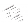
◆FEATURES
t100 Pt200 Pt500 Pt1000 Elements
(100 Ohm/200 Ohm/500 Ohm/1000 Ohm) Ceramic Tube
Pt100 Pt200 Pt 500 Pt 1000 elements to IEC 751 Class A/B
For use from –200°C to +650°C Dip construction
Suitable for surface & immersion applications where protected
Vibration resistant
◆SPECIFICATIONS
Pt1000 Pt200 Pt500 Pt1000 elements to DIN EN 60751:2009-05/IEC 60751 F0.15/ F 0.3 For use from –200°C to +650°CFor use from –200°C to +650°C
Temperature coefficient (TCR) 3850ppm/K
Measuring current 25°C reference recommended current 0.3mA; maximum allowable current 1mA
Lead lengths (L) 10 mm +- 1 mm
Long-term stability max. R0-drift 0.04% after 1000 h at 650°C
Vibration resistance at least 40 g acceleration at 10 to 2000 Hz, depends on installation
Shock resistance at least 100 g acceleration with 8ms half sine wave, depends on installation
Environmental conditions unhoused for dry environments only
Insulation resistance > 100 MW at 20°C; > 2 MW at 500°C
Self heating 0.4 K/mW at 0°C
Response time water current (v = 0.4 m/s): t0.5 = 0.06 s t0.9 = 0.20 sec)
air stream (v = 2 m/s): t0.5 = 3.0 s t0.9 = 13.0 sec)
◆RELIABILITY TEST
●High temperature test : Keep the Pt sensors in +650°C for 1000 hours.
●Low temperature test : Keep the Pt sensors in -200°C for 1000 hours.
●Humidity test : Keep the Pt sensors in 60°C and 90°C to 95% HR for 1000 hours.
●Thermal shock test :
Keep the Pt sensors in 0°C ice water for at least to 15sec, then within 10sec.
Directly put into 100°C hot water for least to 15sec, the above process should
be proceeded for least 10 cycles.
After each item test, valuation of item 1-1 should be within 0.12% and item 1-3
Should exceed 100M at 500V DC.
◆CHARACTERISTICS
●Electrical( Insulation Resistance)
1000M ohm or more The Pt-SMD shall be cramped in the metallic block and tested, as shown below.
Test Voltage: 100V DC for 1 minute at room temperature.
The resistance of a platinum wire with temperature to measure the change in temperature.
The equation for such a change is: R
θ= R
o(1 + αθ + βθ
2)
●where <θ is the temperature change and α and β are constants, β being much smaller than α.
We therefore ignore the term β
2 and assume that the resistance of the wire varies uniformly with temperature: a is the temperature coefficient of resistance of the material. For platinum a = 3.8x10⁻⁴°C -1.
●A simple form of the platinum resistance thermometer is shown in Figure 1. It consists of a platinum wire wound non- inductively on a mica former and held in a glass tube by silica spacers.
The resistance of the wire is measured with a Wheatstone bridge network and to allow for the change in resistance of the leads a set of dummy leads are included in the opposite arm of the bridge (see Figure 2).
●This type of thermometer has a large range, from -200°C to +1100°C and this can
be extended by the use of different wires. Bronze has a range starting at -260°C and
using carbon temperatures as low as -270°C can be measured.
●The advantages of the resistance thermometer are its convenient size, wide range and high sensitivity (0.000 05°C). It can only be used for steady readings, however, and is not direct-reading.
◆Relationship of temperature with Resistance
| When t≧t0°C |
When t <0°C |
| Rt= R0 (1+At Bt2 ) |
Rt= R0 [1+At Bt2+C(t-100) t3] |
| A = 3.9083E-3 |
B = 3.9083-03 |
| B = -5.7750E-07 |
B = -5.7750E-07 |
| |
C = -4.1830E-12 |
| |
R0= 1.000E+02 |
◆ Temperature deviation
●±(a=b ltl) °C
●a= 0.300
●b= 0.005
◆Ordering Information
| Series Code |
Resistance |
Tolerance Class |
| UVP |
100 |
□ |
