


| Test Item | Standard | Test Method | △R25 / R25 | |
| Environmental test |
Life | MIL-STD-202F Method 108A |
Test temperature:70℃ Test duration:1000 hrs Load power:1206 – 6.5 mW,0805 – 5.0 mW,0603 – 4.5 mW,0402 – 3.5 mW。 |
MAX.± 3﹪ |
| Humidity | MIL-STD-202F Method 103B |
Test temperature:40℃ Test humidity:95﹪ Test duration:1000 hrs Load power:1206 – 6.5 mW,0805 – 5.0 mW,0603 – 4.5 mW, 0402 – 3.5 mW。 |
MAX.± 3﹪ | |
| Thermal shock | MIL-STD-202F Method 107G |
Test cycle:10 times Test temperature:- 40℃&125℃ 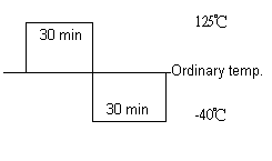 |
MAX.± 3﹪ | |
| Storage in dry heat | IEC 68-2-2 | Test temperature:125℃ Test duration:1000 hrs |
||
| Mechanical Performance test |
Solderability | MIL-STD-202F Method 208 H |
Soldering temperature:235℃ Duration of immersion:2 seconds |
95 ﹪min. coverage |
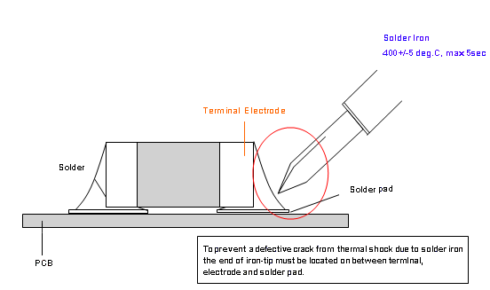
| Resistance to soldering heat | MIL-R-55342D PARA 4.7.7 |
Soldering temperature:260℃ Duration of immersion:10 seconds |
MAX.± 3﹪ | |
| Mechanical Performance test |
Bending strength | JIS C 5202 6.1.4 | Pressurizing rod at a rate of 1mm/sec Maintenance time:5 sec Bending distance:1 mm (min.) 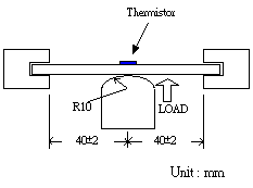 |
Visual : No mechanical damage |
| Resistance to flexure of substrate | JIS C 5202 6.2.1 | Pressurizing force shall be 3kg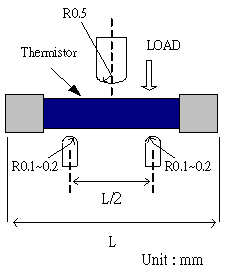 |
MIN. 3 Kg | |
| Electrical Performance test |
Insulation resistance | MIL-STD-202F Method 302 |
DC 250V For 10 seconds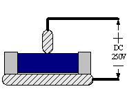 |
Over 1000MΩ |
| Dielectric withstand voltage | MIL-STD-202F Method 301 |
DC 250V For 10 seconds |
NOT Short |
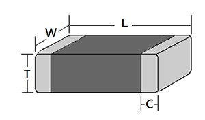
| Size | L[mm] | W[mm] | T[mm] | C[mm] |
| 1005 (0402) | 1.00 ± 0.05 | 0.50 ± 0.05 | 0.50 ± 0.05 | 0.25 ± 0.10 |
| 1608 (0603) | 1.60 ± 0.10 | 0.80 ± 0.10 | 0.80 ± 0.10 | 0.40 ± 0.20 |
| 2012 (0805) | 2.00 ± 0.20 | 1.25 ± 0.20 | 0.80 ± 0.20 | 0.50 ± 0.20 |
| 3216 (1206) | 3.40 ± 0.20 | 1.70 ± 0.20 | 1.40 ± 0.20 | 0.50 ± 0.20 |
| Series Code | Chip Size (mm) | Res. value | Res. Tolerance | B Value | B Tolerance |
| SMD NTC | 02(0402) – 1.0x0.5x0.6 | 101 = 10 x 101 = 100 Ω |
F : ± 1% | 3435 | F : ± 1% |
| F : Lead Free | 03(0603) – 1.6x0.8x0.8 | 102 = 10 x 102 = 1000 Ω |
G : ± 2% | G : ± 2% | |
| 05(0805) – 2.0x1.2x1.2 | 103 = 10 x 103 = 10000 Ω |
H : ± 3% | H : ± 3% | ||
| 06(1206) – 3.2x1.6x1.4 | J : ± 5% | ||||
| K : ± 10% |
| Part Number | Resistance(25℃)(Ω) | B-constant (25-85℃) (k) |
Maximum Power Rating(25℃) (mW) | Thermal Dissipation Constant (mW/℃) | Operating Temp. Range (℃) |
| UT□02300□2600□ | 30 | 2600 | 250 | 2.5 | -40 ~ 125 |
| UT□02300□3250□ | 30 | 3250 | |||
| UT□02330□3250□ | 33 | 3250 | |||
| UT□02470□3250□ | 47 | 3250 | |||
| UT□02680□3250□ | 68 | 3250 | |||
| UT□02101□3250□ | 100 | 3250 | |||
| UT□02221□3250□ | 220 | 3250 | |||
| UT□02102□4100□ | 1.0 K | 4100 | |||
| UT□02152□4100□ | 1.5 K | 4100 | |||
| UT□02202□4100□ | 2.0 K | 4100 | |||
| UT□02202□4520□ | 2.0 K | 4520 | |||
| UT□02222□4100□ | 2.2 K | 4100 | |||
| UT□02302□4100□ | 3 K | 4100 | |||
| UT□02472□3520□ | 4.7 K | 3520 | |||
| UT□02103□3435□ | 10K | 3435 | |||
| UT□02103□3800□ | 10K | 3800 | |||
| UT□02103□3950□ | 10K | 3950 | |||
| UT□02103□4050□ | 10K | 4050 | |||
| UT□02103□4100□ | 10K | 4100 | |||
| UT□02103□4550□ | 10K | 4550 | |||
| UT□02153□3920□ | 15K | 3920 | |||
| UT□02223□3800□ | 22K | 3800 | |||
| UT□02223□4550□ | 22K | 4550 | |||
| UT□02333□4050□ | 33K | 4050 | |||
| UT□02473□3920□ | 47K | 3920 | |||
| UT□02473□4050□ | 47K | 4050 | |||
| UT□02473□4550□ | 47K | 4550 | |||
| UT□02683□4150□ | 68K | 4150 | |||
| UT□02104□4050□ | 100K | 4050 | |||
| UT□02104□4600□ | 100K | 4600 | |||
| UT□02154□4050□ | 150K | 4050 | |||
| UT□02224□4600□ | 220K | 4600 | |||
| UT□02474□4050□ | 470K | 4050 | |||
| UT□02474□4650□ | 470K | 4650 |
| Part Number | Resistance(25℃)(Ω) | B-constant (25-85℃) (k) |
Maximum Power Rating(25℃) (mW) | Thermal Dissipation Constant (mW/℃) | Operating Temp. Range (℃) |
| UT□03220□3050□ | 22 | 3050 | 350 | 3.5 | -40 ~ 125 |
| UT□03300□3200□ | 30 | 3200 | |||
| UT□03330□3200□ | 33 | 3200 | |||
| UT□03400□3200□ | 40 | 3200 | |||
| UT□03470□3200□ | 47 | 3200 | |||
| UT□03680□3200□ | 68 | 3200 | |||
| UT□03101□2800□ | 100 | 2800 | |||
| UT□03101□3250□ | 100 | 3250 | |||
| UT□03221□3250□ | 220 | 3250 | |||
| UT□03102□4150□ | 1 K | 4150 | |||
| UT□03152□4150□ | 1.5 K | 4150 | |||
| UT□03202□4150□ | 2 K | 4150 | |||
| UT□03202□4150□ | 2.2 K | 4150 | |||
| UT□03302□4150□ | 3 K | 4150 | |||
| UT□03472□4150□ | 4.7 K | 4150 | |||
| UT□03472□4500□ | 4.7 K | 4500 | |||
| UT□03502□3250□ | 5 K | 3250 | |||
| UT□03502□3970□ | 5 K | 3970 | |||
| UT□03682□4150□ | 6.8 K | 4150 | |||
| UT□03103□3400□ | 10K | 3400 | |||
| UT□03103□3435□ | 10K | 3435 | |||
| UT□03103□3550□ | 10K | 3550 | |||
| UT□03103□3800□ | 10K | 3800 | |||
| UT□03103□3970□ | 10K | 3970 | |||
| UT□03303□3950□ | 30K | 3950 | |||
| UT□03473□3950□ | 47K | 3950 | |||
| UT□03473□4050□ | 47K | 4050 | |||
| UT□03503□4100□ | 50K | 4100 | |||
| UT□03683□4150□ | 68K | 4150 | |||
| UT□03104□3970□ | 100K | 3970 | |||
| UT□03104□4050□ | 100K | 4050 | |||
| UT□03104□4400□ | 100K | 4400 | |||
| UT□03154□3800□ | 150K | 3800 | |||
| UT□03154□4600□ | 150K | 4600 | |||
| UT□03224□4600□ | 220K | 4600 | |||
| UT□03234□4600□ | 230K | 4100 | |||
| UT□03334□4050□ | 330K | 4050 | |||
| UT□03474□4050□ | 470K | 4050 | |||
| UT□03684□4100□ | 680K | 4750 |
| Part Number | Resistance(25℃)(Ω) | B-constant (25-85℃) (k) |
Maximum Power Rating(25℃) (mW) | Thermal Dissipation Constant (mW/℃) | Operating Temp. Range (℃) |
| UT□05102□3600□ | 1 K | 3600 | 400 | 4 | -40 ~ 125 |
| UT□05202□4100□ | 2 K | 4100 | |||
| UT□05222□4100□ | 2.2 K | 4100 | |||
| UT□05682□3750□ | 6.8 K | 3750 | |||
| UT□05472□4100□ | 4.7 K | 4100 | |||
| UT□05103□3435□ | 10K | 3435 | |||
| UT□05103□3550□ | 10K | 3550 | |||
| UT□05103□3750□ | 10K | 3960 | |||
| UT□05103□3970□ | 10K | 3970 | |||
| UT□05153□4050□ | 15K | 4000 | |||
| UT□05333□3950□ | 33K | 3950 | |||
| UT□05473□3950□ | 47K | 3950 | |||
| UT□05473□4050□ | 47K | 4050 | |||
| UT□05503□4100□ | 50K | 4100 | |||
| UT□05683□3800□ | 68K | 3800 | |||
| UT□05104□3977□ | 100K | 3977 | |||
| UT□05104□4050□ | 100K | 4050 | |||
| UT□05224□4100□ | 220K | 4100 | |||
| UT□05234□4100□ | 230K | 4100 | |||
| UT□05334□4100□ | 330K | 4100 | |||
| UT□05474□4100□ | 470K | 4100 | |||
| UT□05684□4100□ | 680K | 4100 |
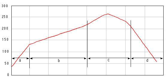
| Zone | Temp. range [deg. C] | time [sec] | Remark | |
| a | Curing | RT ~ | 60 90 ~ 150 90 ~ 150 min 60 |
* Solder : Sn-Ag-Cu * 260deg. C, over 10 |
| b | Preheat | max | ||
| c | Soldering | 220 ~ 260 [max 270] | ||
| d | Cooling | 220 ~ | ||
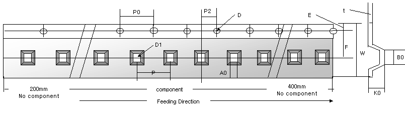
| Size | A0 | B0 | W | D1 | E | F | P | P0 | P2 | t |
| 1005 | 0.65±0.10 | 1.15±0.10 | 8.00±0.20 | 1.50±0.25 | 1.75±0.10 | 3.50±0.50 | 4.0±0.10 | 4.0±0.10 | 2.0±0.10 | 0.23±0.10 |
| 1608 | 1.10±0.10 | 1.90±0.10 | ||||||||
| 2012 | 1.50±0.10 | 2.35±0.10 | ||||||||
| 3216 | 1.80±0.10 | 3.50±0.10 |
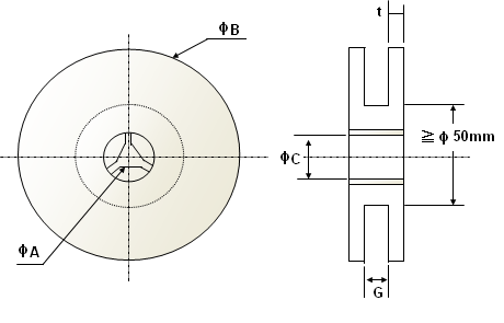
| Chip size | ΦA | ΦB | ΦC | G | t |
| ≤ 2012 | 178±2.0 | 13.0±0.5 | 22.0±2.0 | 10.0±1.5 | 2.5±0.5 |
| Dimension | 1005 (0402) | 1608 (0603) | 2012 (0805) | 3216 (1206) | Carrier Tape |
| pcs/reel | 10,000 | 4,000 | 4,000 | 3,000 | Paper |